CNC Milling Guide Process Types Materials and Tolerances
You already know that CNC milling is the backbone of high-precision manufacturing.
But when you’re designing complex parts or sourcing a reliable production partner, the technical nuances can get overwhelming. What are the strict geometric tolerances a 5-axis setup can actually hit? Which engineering materials will drive up your machining costs, and which will streamline production?
I’ve broken down the essential capabilities, material compatibilities, and mechanical frameworks of computer numerical control milling. Whether you’re optimizing a CAD file for production or evaluating outsourcing capabilities, this guide cuts through the noise to give you the exact precision engineering data you need.
Let’s dive right in.
How CNC Milling Works: The Core Workflow
At its core, CNC milling is a highly precise subtractive manufacturing process. We take a solid block of raw material and systematically carve it away to reveal a finished, high-precision part.
Here is exactly how our team transforms a digital concept into a physical component through an optimized CAD/CAM software integration workflow.
1. Digital Architecture & DFM
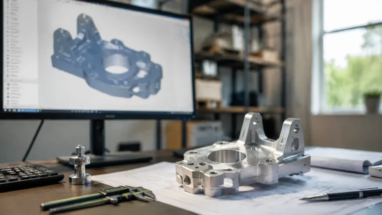
Every project begins with a 3D model created via Computer-Aided Design (CAD). Before moving forward, we apply Designing for Manufacturability (DFM) principles. This step ensures the part geometry can be machined efficiently, minimizing material waste and reducing production costs.
2. Toolpath Generation (CAM)
Once the design is locked in, we move it into Computer-Aided Manufacturing (CAM) software. Here, we perform toolpath optimization to plot the most efficient routes for the cutting tools. The software translates the 3D model into a precise digital blueprint using G-code and M-code execution commands, which tell the machine exactly where to move, how fast to spin, and when to change tools.
3. Machine Setup and Fixturing
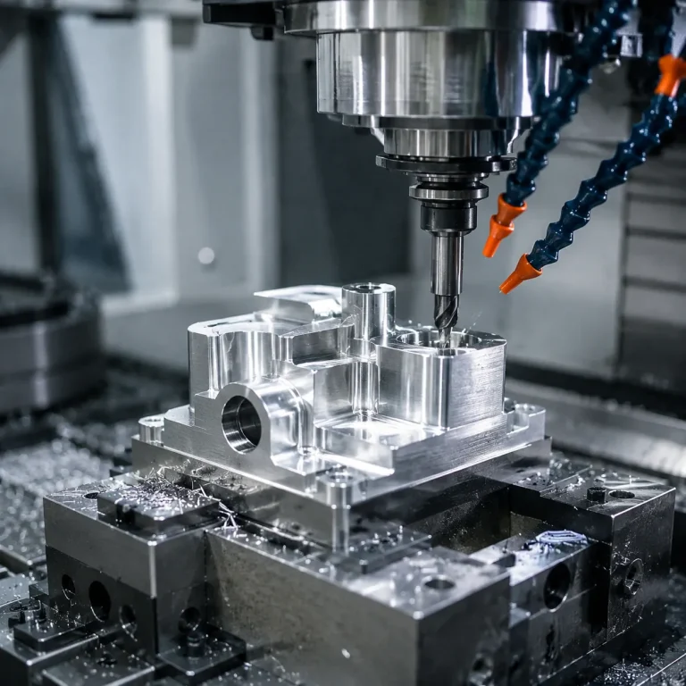
Before the spindle turns, the raw stock must be perfectly aligned. We secure the material using specialized workpiece holding and fixturing setups, such as vises, clamps, or custom fixtures. This guarantees zero shifting under heavy cutting forces, maintaining strict dimensional accuracy.
4. Material Removal Phase
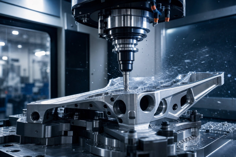
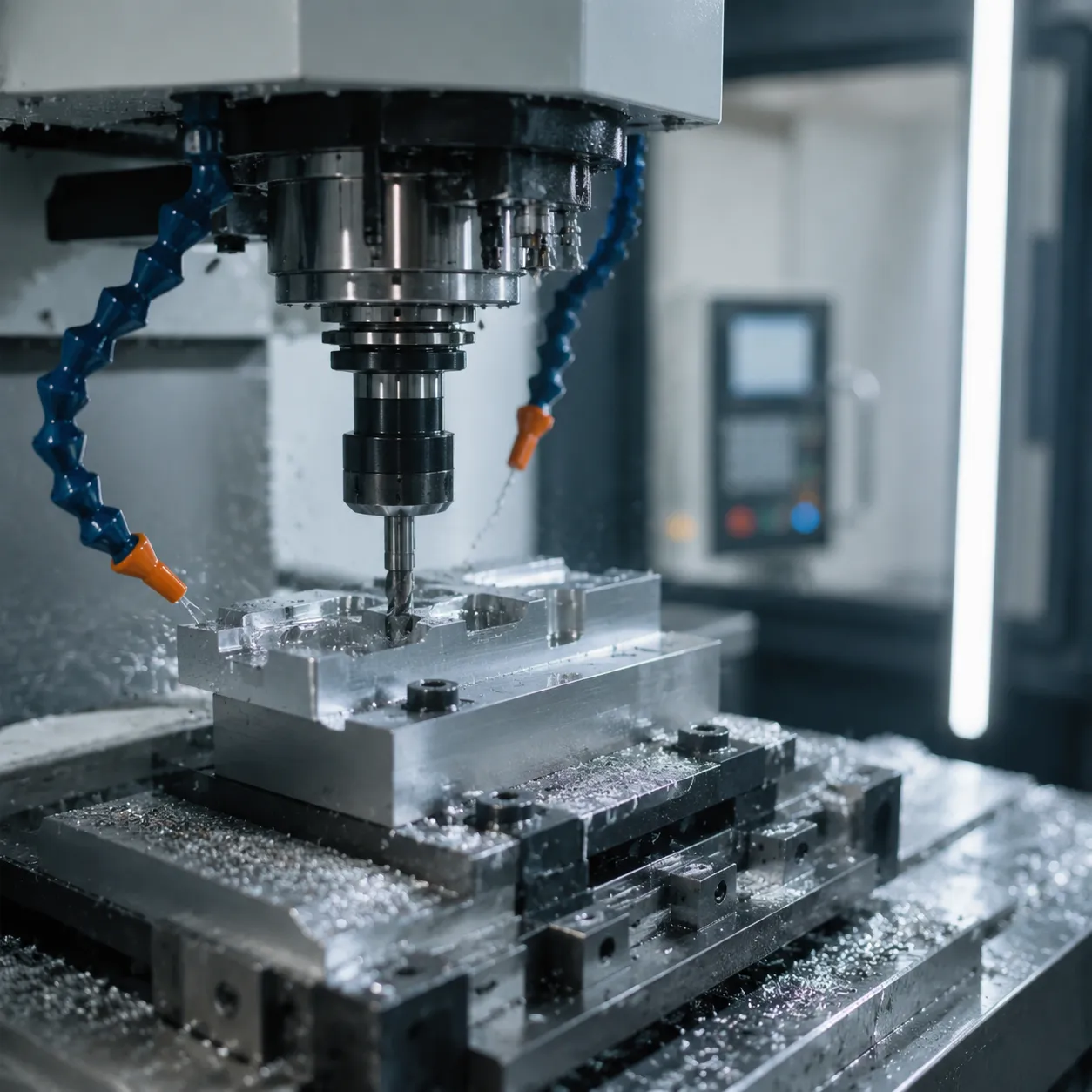
With the program loaded and the stock secured, the milling begins. The machine executes the pre-programmed cutting paths, removing material layer by layer. During this phase, we use continuous coolant delivery to manage thermal stability, clear away chips, and protect both the cutting tool and the workpiece surface.
5. Post-Processing
After the machining cycle finishes, the component enters the final stage. We extract the part from the fixtures and perform secondary finishing operations to remove any burrs, smooth out surfaces, and prepare the component for final quality inspection.
Types of CNC Milling Operations
When we set up our multi-axis machining centers, choosing the right cutting approach is everything. Different geometries require distinct cutting methods to maximize the material removal rate (MRR) while protecting our tools.
Here is how we break down the core CNC milling operations to achieve ultimate dimensional accuracy:
- Face Milling: We use this to cut flat surfaces perpendicular to the cutter’s axis. It is our go-to method for creating perfectly smooth, flat faces on raw stock before starting detailed work.
- Peripheral (Plain) Milling: Here, the cutting action happens parallel to the workpiece periphery. We use the sides of the tool to shave off material, which is ideal for squaring up outer blocks.
- Pocketing and Slotting: This operation carves out closed boundaries and deep channels. We rely on smart toolpath optimization here to clear out deep internal cavities without breaking the tool.
- Contour Milling: For complex, curved surfaces and non-linear shapes, we use contouring. The machine follows intricate 3D paths to produce smooth, organic geometric profiles.
Machine Configurations in CNC Milling
When you are looking to bring a design to life, choosing the right machine setup is everything. In our shops, we utilize different multi-axis machining centers depending on how complex your part is, how much material we need to cut, and your budget.
3-Axis Machining
This is the bedrock of subtractive manufacturing. A standard 3-axis setup moves the cutting tool along three basic axes: X (left to right), Y (front to back), and Z (up and down).
- Best for: Standard prismatic parts, flat profiles, and straightforward brackets.
- How it works: The workpiece remains stationary on the machine bed while the spinning tool cuts away material from above.
- The Catch: If you need features machined on multiple sides of the part, we have to manually stop the machine, flip the workpiece, and re-fixture it. This adds setup time but keeps initial tooling costs low.
4-Axis Machining
To speed things up and tackle trickier geometries, we introduce a fourth axis of motion—typically the A-axis, which rotates around the X-axis.
- Best for: Cylindrical details, continuous engraving, and angled cuts on the sides of a part.
- How it works: The machine holds the raw stock in a rotary chuck. As the tool moves in X, Y, and Z, the part rotates simultaneously.
- The Advantage: It allows for complex indexing. We can machine four sides of a component without manual repositioning, ensuring tighter part-to-part dimensional accuracy.
5-Axis Machining
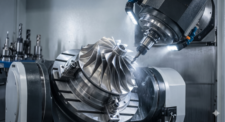
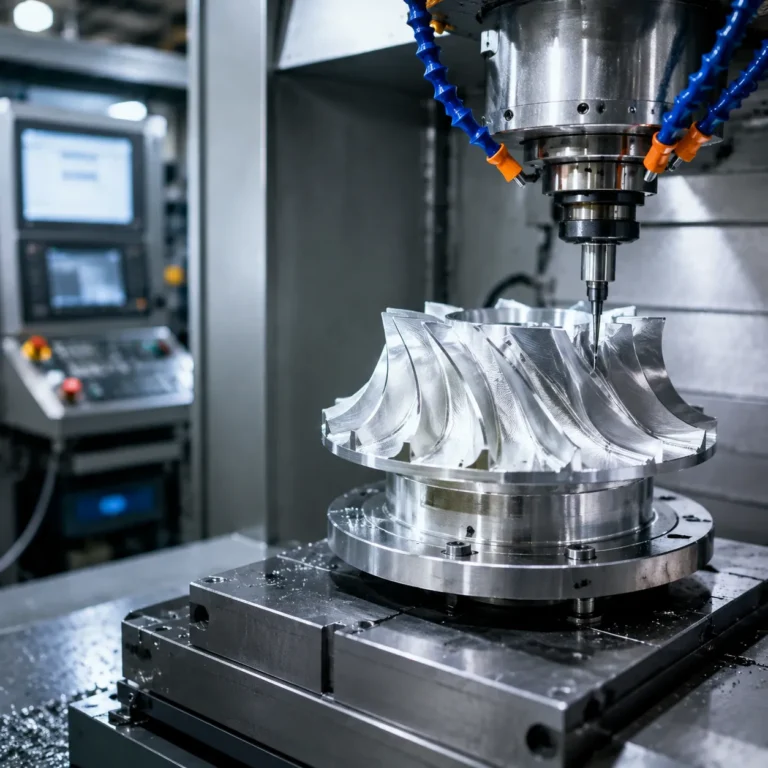
For total geometric freedom, 5-axis CNC milling utilizes two additional rotational axes (usually a combination of B and C, or A and C) along with the standard X, Y, and Z.
- Best for: Complex aerospace-grade alloys, impellers, medical implants, and highly organic, curved surfaces.
- How it works: The cutting tool and the workpiece can move and tilt relative to each other in every direction at the exact same time.
- The Advantage: Single-setup execution. We can machine incredibly intricate, deep pockets and undercuts in one continuous operation. This drastically improves your material removal rate (MRR), eliminates human error from multiple setups, and delivers an exceptional surface roughness average (Ra).
Choosing the Right Materials for CNC Milling
When we handle CNC milling projects for our global clients, selecting the right raw stock is the most critical decision we make. In subtractive manufacturing, your material choice dictates your tool life, production speed, and final part performance.
Metals: From Aluminum to Aerospace Alloys
We process a wide range of metals to meet strict engineering demands across industries:
- Aluminum (6061 / 7075): The go-to choice for rapid prototyping and production. It offers excellent machinability and a great strength-to-weight ratio.
- Stainless Steel (304 / 316): Chosen for its corrosion resistance and strength, though it requires rigid setups and slower speeds.
- Brass & Copper: Highly conductive and easy to machine, perfect for electrical components and custom hardware.
- Titanium: A premium aerospace-grade alloy valued for its extreme strength and biocompatibility, demanding specialized cutting strategies.
Advanced Engineering Plastics
For lightweight components, insulation, or chemical resistance, we utilize high-performance engineering plastics (Delrin, PEEK):
- Delrin (POM): Exceptionally easy to machine with high dimensional stability and low friction.
- Nylon: Tough and wear-resistant, ideal for durable mechanical parts like gears.
- PEEK: A top-tier thermoplastic capable of withstanding extreme temperatures and harsh chemicals.
- Polycarbonate & PTFE: Chosen for optical clarity (Polycarbonate) or exceptional chemical inertness and lubrication (PTFE).
Critical Material Selection Factors
To optimize the material removal rate (MRR) and ensure part quality, we evaluate three primary metrics before starting any CNC milling job:
| Selection Factor | Engineering Impact |
|---|---|
| Hardness | Determines tool wear and the required cutting forces. |
| Machinability Index | Indicates how easily a material can be cut relative to a standard reference metal. |
| Thermal Stability | Prevents part warping or dimensional drifting due to heat buildup during high-speed cutting. |
Engineering Tolerances and Surface Finishes in CNC Milling
When we manufacture precision parts, getting the exact dimensions and the right feel on the surface isn’t optional—it’s a requirement. High-precision CNC milling allows us to hit tight specs consistently, whether we are building rapid prototypes or moving into full-scale mass production.
Achievable Precision: Dimensional Accuracy
We routinely master strict dimensional accuracy down to ±0.01 mm on our multi-axis machining centers. Achieving this level of precision depends heavily on choosing the right material, maintaining rigid workpiece holding, and accounting for tool deflection. We design with Geometric Dimensioning and Tolerancing (GD&T) principles to ensure every part fits perfectly into your final assembly.
Surface Roughness (Ra): Controlling Spindle Speed and Feed Rates
The finish of a machined part depends on your cutting parameters. By finely tuning the spindle speed and feed rates, we directly control the surface roughness average (Ra). Balancing these factors optimizes the material removal rate (MRR) while eliminating unwanted chatter marks.
| Factor | Impact on Surface Roughness (Ra) | Best Practice for High Quality |
|---|---|---|
| Spindle Speed | Higher speeds reduce friction and prevent built-up edges. | Increase for a smoother, mirror-like finish. |
| Feed Rate | Slower feed rates reduce the pitch of tool marks. | Decrease during the final finishing pass. |
| Toolpath Optimization | Determines how the cutter engages with the material. | Use constant-engagement paths to prevent surface gouges. |
Post-Machining Options: Secondary Finishing
Sometimes the raw machine finish is just the starting point. We offer several post-machining and surface treatment options to improve both the look and durability of your components:
- Anodizing: Adds a protective, corrosion-resistant oxide layer to aluminum parts, available in clear or colored finishes.
- Bead Blasting: Uses fine glass beads to create a uniform, matte satin finish that hides tool marks.
- Passivating: Removes free iron from the surface of stainless steel to maximize its natural rust resistance.
- Electroplating: Deposits a thin layer of another metal (like nickel or chrome) onto the part to improve wear resistance or electrical conductivity.
Sourcing Quality: Metrology and Inspection Protocols
When you source custom parts from our CNC milling platform, precision isn’t just a goal—it is a guarantee. We back every production run with strict quality control protocols to ensure every cut, slot, and thread matches your exact blueprint.
Multi-Stage Inspection Lifecycles
We catch deviations before they become defects. Our multi-stage inspection lifecycle ensures dimensional accuracy from the initial machine setup all the way to final delivery.
- Active Setup Sampling: Machining centers undergo first-article inspection to validate tool offsets and programs before mass production begins.
- In-Process Monitoring: Operators perform routine checks during the manufacturing run to monitor tool wear and prevent drift.
- Pre-Shipment Clearance: Every batch undergoes strict quality control checks against your CAD model before we pack and ship your parts.
Advanced Instrumentation
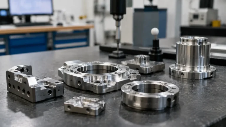
We rely on industrial-grade metrology equipment to verify the tightest tolerances on complex geometries.
| Instrument | Primary Function | Target Metric |
|---|---|---|
| Coordinate Measuring Machines (CMM) | Automated 3D coordinate scanning | Complex geometric profiles |
| Digital Micrometer Arrays | High-precision thickness and diameter checks | Linear dimensions down to ±0.01 mm |
| Surface Profilometers | Stylus-based micro-roughness measurement | Surface roughness average (Ra) |
By pairing advanced Coordinate Measuring Machines (CMM) with active visual inspections, we deliver reliable, high-performance parts that fit perfectly right out of the box.
CNC Milling FAQs
When we manufacture custom parts for our global clients, a few core questions come up time and again. We keep our subtractive manufacturing processes transparent, so here are the direct answers to your most frequent CNC milling questions.
CNC Milling vs. CNC Turning
The main difference lies in which part moves: the cutting tool or the workpiece.
| Process | Core Mechanism | Best Used For |
|---|---|---|
| CNC Milling | The workpiece stays stationary while the cutting tool rotates to remove material. | Complex, blocky, or asymmetrical shapes with pockets and slots. |
| CNC Turning | The workpiece rotates at high speeds while a stationary cutting tool shapes it. | Cylindrical, round, or symmetrical parts like shafts and pins. |
What materials are hardest to machine in CNC milling?
Titanium and nickel-based superalloys (like Inconel) are the most challenging. Because of their extreme hardness and low thermal conductivity, they generate intense heat at the cutting edge. This accelerates tool wear and requires precise spindle speed and feed rates, specialized tool coatings, and high-pressure coolant to manage.
How do feed rates affect surface roughness average (Ra)?
Your feed rate directly dictates your final surface roughness average (Ra).
- Faster Feed Rates: Save time but increase the spacing between tool marks, leading to a rougher surface finish.
- Slower Feed Rates: Allow the cutting tool to overlap its paths more tightly, significantly lowering the Ra value for a smoother, high-quality finish.
What are the standard tolerances for custom machined parts?
For typical multi-axis machining centers, standard commercial tolerances sit comfortably at ±0.125 mm (±0.005 inches). When your application demands higher precision, we achieve tight dimensional accuracy down to ±0.01 mm (±0.0004 inches), ensuring strict adherence to your Geometric Dimensioning and Tolerancing (GD&T) blueprints.