Why Custom CNC Machining Parts For Aerospace Applications Get Rejected
What Makes Custom CNC Machining Essential for Aerospace
Custom CNC machining parts for aerospace applications are not the same as standard production runs you’d find in automotive or consumer electronics. In aerospace, you’re dealing with low-volume, high-mix components where every single part carries unique geometry, material requirements, and documentation demands. Think of it this way: a commodity machine shop optimizes for speed and volume. An aerospace CNC machining operation optimizes for precision, traceability, and zero-defect delivery.
If you’re an engineer specifying parts or a buyer sourcing them, understanding this distinction matters. It determines how you write specs, evaluate suppliers, and plan timelines. Get it wrong, and parts get rejected before they ever reach assembly.
Why Aerospace Demands Custom Machined Parts
Aerospace components operate in environments that punish even minor compromises. Temperature swings from -250°C to over 700°C, sustained vibration loads, corrosive atmospheres, and fatigue cycles measured in decades. These constraints drive material choices that are inherently difficult to machine, like titanium and nickel superalloys.
Weight optimization adds another layer. Every gram removed from an airframe translates to fuel savings over the aircraft’s lifetime. That means thin walls, complex pockets, and topology-driven geometries that demand custom aerospace machining strategies rather than off-the-shelf approaches. Layer on the regulatory burden of AS9100 compliance, full material traceability, and first article inspection requirements, and you’ll see why cnc machining for aerospace operates in a fundamentally different category than general-purpose production.
How Custom CNC Differs from Standard Production Runs
Standard CNC production focuses on cycle time reduction and fixture optimization for thousands of identical parts. Custom aerospace work flips that priority. Here, the workflow centers on design iteration, prototype validation, and a documented pathway from first article to qualified production.
Imagine sending a revised CAD model to your machining partner three times before locking the design. Each iteration requires updated CAM programming, new inspection protocols, and traceable documentation that links every revision to specific material lots and process parameters. That iterative loop, supported by DFM feedback from experienced shops, is what separates aerospace machining solutions from commodity work.
The more complex the part geometry and the tighter the performance envelope, the less viable standard production methods become. Custom CNC machining exists precisely because aerospace parts refuse to fit into repeatable, high-volume templates.
Traceability ties the entire process together. Every aerospace CNC machined component must carry a complete history: which billet it came from, who programmed the toolpath, what cutting parameters were used, and which inspector signed off. This level of documentation doesn’t exist in standard production environments because it doesn’t need to. In aerospace, it’s non-negotiable.
These foundational differences in environment, workflow, and documentation set the stage for every downstream decision, starting with the materials that make cnc machining aerospace parts so technically demanding.
Aerospace Materials and Their Machinability Challenges
Material selection in aerospace is never arbitrary. Each alloy earns its place because it solves a specific engineering problem, whether that’s surviving 1,200°F exhaust streams or shaving weight from a wing spar. But the same properties that make these materials perform in flight also make them punishing to cut. Understanding machinability challenges is essential for anyone involved in machining for aerospace, because tool wear behavior and cutting strategy directly determine whether a part passes inspection or gets scrapped.
Titanium Ti-6Al-4V and Tool Wear Considerations
Ti-6Al-4V dominates structural airframe components, landing gear fittings, and fasteners for one reason: it delivers steel-level strength at roughly 60% of the weight. That strength-to-weight advantage is unmatched for parts that carry heavy loads while keeping aircraft light.
The machining difficulty comes from titanium’s low thermal conductivity. Unlike aluminum, which pulls heat away from the cutting zone, titanium traps thermal energy right at the tool tip. The result is rapid edge degradation and a tendency toward work hardening if feed rates drop too low. Cutting speeds typically stay between 100-200 SFM with carbide tooling, and tool life is measured in minutes rather than hours. Sharp tools, rigid setups, and aggressive coolant delivery are non-negotiable. Hesitate on any of those, and the work-hardened surface layer becomes harder than the cutting tool itself.
Nickel Superalloys for High-Temperature Engine Components
When temperatures exceed what titanium can handle, nickel superalloys take over. Inconel 718 retains tensile strength above 180 ksi at temperatures where aluminum would be liquid and titanium begins oxidizing. That heat resistance makes it indispensable for turbine discs, combustion chambers, and exhaust components.
The trade-off is extreme. Inconel 718 scores just 12% on the AISI Machinability Index, making it one of the most difficult metals to cut reliably. Three problems compound simultaneously: the austenitic structure work-hardens under deformation, poor thermal conductivity concentrates heat at the cutting edge, and high cutting forces stress the entire machine system. Tool life drops to 20-40 minutes of actual cutting time, and carbide tools with TiAlN or AlTiN coatings are essential. Precision machining for aerospace engine components in these alloys demands conservative speeds of 60-100 SFM, high-pressure coolant at 500+ PSI, and continuous cutting strategies that avoid re-entering work-hardened surfaces.
Aluminum 7075-T6 for Weight-Critical Structures
Not every aerospace component needs exotic alloys. Aluminum 7075-T6 remains the workhorse for brackets, avionics housings, wing ribs, and fuselage bulkheads where strength-to-weight ratio matters but operating temperatures stay moderate. Its tensile strength approaches that of structural steel while weighing a fraction as much.
From an aircraft machining perspective, 7075 is a relief. It cuts cleanly, produces manageable chips, and allows high spindle speeds that keep cycle times reasonable. Tool wear is significantly lower than titanium or nickel alloys. The primary challenges are controlling heat to prevent dimensional distortion in thin-walled sections and managing the material’s susceptibility to corrosion, which requires post-machining treatments like anodizing. For aerospace precision machining operations, 7075-T6 offers favorable economics without sacrificing the mechanical performance that flight-critical structures demand.
Alloy | Typical Application | Machinability Rating | Key Challenge | Preferred CNC Strategy |
Ti-6Al-4V | Airframe structures, landing gear, fasteners | ~22% (AISI Index) | Low thermal conductivity, work hardening | Low speed, high feed, rigid setup, flood coolant |
Inconel 718 | Turbine discs, combustion chambers, exhaust systems | ~12% (AISI Index) | Extreme heat at tool tip, rapid work hardening, high cutting forces | Conservative speed (60-100 SFM), continuous cuts, high-pressure coolant (500+ PSI), coated carbide tooling |
Inconel 625 | Exhaust ducting, combustion liners, corrosive-environment parts | ~17% (AISI Index) | Heat concentration, material adhesion to tools | Similar to 718 with slightly higher allowable feeds |
Aluminum 7075-T6 | Wing ribs, brackets, avionics housings, bulkheads | ~70-80% (AISI Index) | Thin-wall distortion, corrosion vulnerability | High speed, sharp tooling, minimal heat input, anodize post-machining |
Each of these materials responds differently to cutting forces, heat, and tool geometry. That variability is exactly why precision aerospace machining requires process planning tailored to the specific alloy, not generic parameters pulled from a handbook. A strategy that works beautifully on 7075 aluminum will destroy tooling in seconds on Inconel 718.
Material choice also cascades into another critical decision: how the part gets classified for inspection and documentation. A titanium landing gear fitting and an aluminum interior bracket face vastly different quality requirements, and those requirements reshape the entire machining and verification workflow.
Part Criticality Classifications and Their Impact on Machining
A titanium turbine blade and an aluminum cabin bracket might both qualify as aerospace machined parts, but they live in completely different worlds when it comes to quality requirements. The dividing line? Part criticality classification. This single designation, assigned during design review, dictates how a component gets machined, inspected, documented, and ultimately accepted or rejected. Miss the classification requirements, and even a dimensionally perfect part ends up in the scrap bin.
For engineers and buyers specifying machined parts to aerospace standards, understanding criticality tiers isn’t optional. It’s the framework that determines your cost, lead time, and supplier qualification requirements before a single chip gets cut.
Flight-Critical vs Mission-Critical vs Non-Critical Designations
Aerospace part classifications typically fall into three tiers, each defined by the consequences of failure during operation.
Flight-critical parts are components whose failure could result in catastrophic damage to the aircraft or loss of life. As Monroe Aerospace explains, these are parts that airplanes need to safely fly, and their failure may result in catastrophic outcomes such as engine shutdown. Regulatory bodies like the FAA and EASA maintain strict guidelines governing their production and use. Examples include turbine blades, landing gear fittings, wing spar attachments, engine mounts, and cooling fins on powerplant assemblies.
Mission-critical parts won’t bring an aircraft down if they fail, but they compromise the aircraft’s ability to complete its intended function. Think avionics enclosures that house navigation systems, radar housings, or hydraulic manifolds. The aircraft can still fly safely, but the mission gets aborted or degraded.
Non-critical parts have no direct impact on flight safety or mission capability. Interior brackets, cabin trim fasteners, and galley mounting hardware fall here. Their failure creates maintenance issues or cosmetic problems, not safety events.
How does a part earn its classification? During design review, engineering teams evaluate failure modes using tools like FMEA (Failure Mode and Effects Analysis). They ask a straightforward question: if this component fails completely during flight, what happens? The answer places it in the appropriate tier, and that designation follows the part through every stage of production.
How Classification Drives Machining and Inspection Requirements
Here’s where classification gets practical. A flight-critical landing gear fitting machined from Ti-6Al-4V doesn’t just need tighter tolerances. It needs a fundamentally different production and verification infrastructure than a non-critical interior bracket cut from 6061 aluminum. The requirements escalate dramatically at each tier:
- Documentation depth:Flight-critical aircraft machined parts require full material traceability back to the original melt source, certified material test reports, and complete process records for every operation. Mission-critical parts need material certs and process documentation but may allow batch-level rather than piece-level traceability. Non-critical parts typically require standard material certifications only.
- Inspection frequency:Flight-critical aerospace machined components demand 100% inspection, meaning every single feature on every single part gets measured and verified. Mission-critical parts may use statistical sampling with tighter AQL (Acceptable Quality Level) values. Non-critical parts often allow standard sampling-based QC per ANSI/ASQ Z1.4.
- Surface finish verification:Flight-critical parts require documented surface roughness measurements at specified locations, since surface finish directly affects fatigue life. Mission-critical parts need surface finish verification on functional surfaces. Non-critical parts may only require visual inspection for obvious machining defects.
- Non-destructive testing mandates:Flight-critical parts often require fluorescent penetrant inspection (FPI), ultrasonic testing, or X-ray examination to detect subsurface flaws invisible to dimensional inspection. Mission-critical parts may require NDT on high-stress features only. Non-critical parts rarely require any NDT unless specified by the customer.
- First Article Inspection (FAI):Flight-critical parts require comprehensive FAI reports per AS9102, documenting every dimension, material property, and process parameter. Mission-critical parts need FAI but may allow reduced scope. Non-critical parts may only require dimensional verification against key characteristics.
You’ll notice the pattern: as criticality increases, so does every cost and time multiplier in the production workflow. A flight-critical part might require three times the inspection labor of an identical geometry classified as non-critical. That’s not waste or bureaucracy. It’s the direct cost of ensuring that aerospace machined components perform without failure in service.
For buyers, the practical takeaway is clear. When you send a drawing to a machine shop, the criticality classification must be explicitly stated. Shops that produce machined parts to aerospace standards will build their entire process plan, from fixturing strategy to final inspection protocol, around that designation. Omit it, and you’re inviting either over-engineering that inflates cost or under-documentation that guarantees rejection at receiving inspection.
Criticality classification sets the quality framework, but it doesn’t tell the machinist how tight to hold each dimension. That answer depends on the component’s function, and tolerance requirements vary dramatically between a structural airframe bracket and a rotating turbine component operating at 40,000 RPM.
Tolerance Requirements Organized by Aerospace Component Type
Generic claims about “micron-level precision” don’t help you specify parts or evaluate suppliers. What matters is knowing the actual tolerance range your component category demands and why that number exists. The functional driver behind each tolerance requirement determines whether a shop can realistically hold it, and whether the cost is justified for your application.
When machining aerospace parts, tolerance decisions aren’t arbitrary. They flow directly from how the finished component behaves in service: how it fits into an assembly, how it handles cyclic stress, or how it manages thermal and electromagnetic energy. Here’s how those requirements break down by component type.
Structural Component Tolerances
Airframe brackets, wing ribs, spars, and bulkhead fittings typically require dimensional tolerances of ±0.01 mm for general profiles and ±0.005 mm for critical fit features. These numbers exist for two reasons: assembly fit and fatigue life.
Assembly fit matters because structural components bolt, rivet, or bond into larger assemblies with dozens of mating surfaces. If a wing rib deviates beyond its tolerance band, it creates stress concentrations at fastener holes and mating interfaces. Those concentrations become fatigue crack initiation sites over thousands of pressurization cycles.
Fatigue life is the second driver. Surface finish on structural parts typically needs to stay at Ra 1.6 µm or better on load-bearing surfaces, because rougher finishes create micro-notches that accelerate crack propagation. For precision machined aerospace components in primary structure, the tolerance isn’t about looking good on paper. It’s about ensuring the part survives 30+ years of cyclic loading without developing cracks that ground the aircraft.
Engine and Turbine Part Tolerances
Rotating engine components operate in a different universe. A turbine disc spinning at 40,000 RPM amplifies any mass imbalance into destructive vibration. That’s why precision machining aerospace engine parts demands tolerances of ±0.005 mm or tighter on critical diameters and balance features, with some seal interfaces requiring ±0.0025 mm.
Surface finish requirements tighten accordingly. Turbine blades and disc slots typically specify Ra 0.4-0.8 µm to minimize aerodynamic drag and prevent fatigue initiation in the high-temperature, high-stress environment. As research on CNC tolerances notes, even a 0.0005-inch variation in a turbine blade can disrupt aerodynamics and compromise performance.
The combination of exotic materials like Inconel 718 and ultra-tight tolerances makes engine components the most demanding category in aerospace parts machining. Every dimension carries safety implications because imbalance at turbine speeds generates forces that can fracture housings and destroy entire engine modules.
Avionics Housing Dimensional Requirements
Avionics enclosures face a different set of drivers. EMI shielding effectiveness depends on how tightly mating surfaces come together. Gaps at seams allow electromagnetic energy to leak in or out, potentially disrupting navigation, communication, or flight control systems. That’s why precision aerospace CNC machined parts for avionics housings typically hold tolerances of ±0.02 mm on mating flanges and sealing surfaces, with high-performance applications pushing to ±0.1 mm on general features and tighter on critical interfaces.
Thermal management adds another constraint. Electronic components generate heat that must conduct efficiently through the enclosure walls. Uneven wall thickness or poor flatness creates thermal bottlenecks that cause hot spots and premature component failure. Flatness tolerances on mounting surfaces often need to stay within 0.05 mm across the full face to ensure consistent thermal contact.
Component Category | Typical Tolerance Range | Surface Finish Requirement | Functional Driver |
Structural (brackets, ribs, spars) | ±0.005 to ±0.01 mm | Ra 0.8-1.6 µm | Assembly fit, fatigue crack prevention |
Engine/Turbine (discs, blades, seals) | ±0.0025 to ±0.005 mm | Ra 0.4-0.8 µm | Rotational balance, aerodynamic performance, thermal cycling |
Avionics housings (enclosures, chassis) | ±0.02 to ±0.1 mm | Ra 1.6-3.2 µm | EMI shielding continuity, thermal contact |
Landing gear fittings | ±0.005 to ±0.01 mm | Ra 0.8-1.6 µm | Load distribution, fatigue life under impact |
Hydraulic manifolds | ±0.01 to ±0.025 mm | Ra 0.4-0.8 µm (ports) | Seal integrity, pressure containment |
Notice the pattern: the closer a component operates to failure-inducing conditions (high speed, high stress, high temperature), the tighter its tolerances become. Aerospace CNC machined parts for engine applications can cost five to ten times more per feature than equivalent geometry on a structural bracket, and the tolerance hierarchy explains why.
Knowing what tolerance class your part falls into is only half the equation. The other half is selecting the CNC process capable of achieving those numbers reliably, because a 5-axis mill, a CNC lathe, and a wire EDM machine each excel in different tolerance and geometry combinations.
Selecting the Right CNC Process for Your Aerospace Part
Tolerance class tells you how tight a feature needs to be. But it doesn’t tell you which machine should cut it. A turbine blisk with compound-curved airfoils, a landing gear shaft with concentric diameters, and a fuel nozzle with micro-channels each demand fundamentally different CNC processes. Choosing wrong doesn’t just inflate cost. It produces parts that fail inspection because the process itself can’t reliably hold the required geometry.
Here’s how to match your part’s characteristics to the right cnc aerospace capability.
Multi-Axis Milling for Complex Geometries
When does aerospace milling require 5-axis simultaneous capability versus a simpler 3-axis setup? The answer comes down to surface complexity and access angles.
3-axis milling handles parts with features oriented primarily in one direction: flat pockets, stepped profiles, and through-holes on a single face. Structural brackets, simple ribs, and mounting plates are typical candidates. The equipment costs less, programming is straightforward, and cycle times stay predictable. For many milled parts in non-critical structural roles, 3-axis is the economically sound choice.
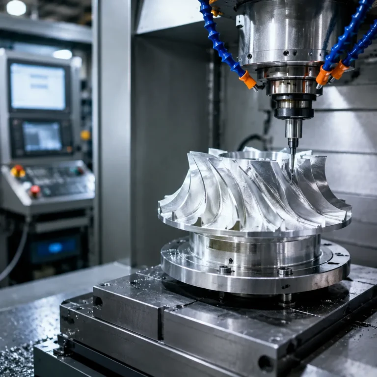
5-axis machining becomes necessary when geometry demands tool access from multiple angles in a single setup. Turbine blisks, impellers, complex structural nodes, and aerodynamic surfaces with compound curvature all fall here. As manufacturing case studies demonstrate, 5-axis single-setup machining eliminates the cumulative positioning errors that plague multi-setup 3-axis approaches, and can reduce lead times by 35% or more on complex aerospace cnc milling jobs. The trade-off is higher programming complexity and machine-hour rates, but for parts where positional accuracy between features is critical, the total cost often favors 5-axis because it eliminates rework.
CNC Turning for Rotational Aerospace Components
Shafts, bushings, fittings, and fasteners share a common trait: rotational symmetry. CNC turning is the primary operation for these components, and in cnc machining aerospace applications, precision lathes routinely hold diameters to ±0.005 mm with surface finishes below Ra 0.8 µm.
Modern CNC lathes with live-tooling capability blur the line between turning and milling. A landing gear pin that needs both precision diameters and cross-drilled holes can be completed in a single setup rather than moving between a lathe and a mill. Fewer setups mean fewer datum shifts, tighter feature-to-feature accuracy, and shorter cycle times. For cnc machining aircraft parts with predominantly cylindrical geometry plus secondary features like flats, keyways, or off-axis holes, live-tooling lathes offer the best balance of precision and efficiency.
Wire EDM and Specialty Processes for Difficult Features
Some features simply can’t be achieved through conventional milling or turning. Wire EDM fills that gap for aircraft cnc machining applications where material hardness, feature geometry, or wall thickness pushes beyond what rotary cutting tools can manage.
Wire EDM achieves tolerances within microns on hardened superalloys without introducing mechanical stress. It excels at thin-walled structures, high-aspect-ratio slots, and intricate profiles in materials like Inconel and hardened tool steels. Turbine blade root forms, fir-tree slots in discs, and cooling channel geometries are common applications. Sinker EDM handles deep cavities and internal geometries that no end mill can reach, making it essential for fuel system components and complex die features.
The key advantage of EDM for aerospace? No cutting force contacts the workpiece. That means zero work hardening, no deformation of delicate features, and no risk of inducing residual stresses that compromise fatigue life.
Process Selection Decision Framework
When you’re evaluating which process fits your part, work through these factors in sequence:
- Assess geometry complexity:Is the part primarily 2D/2.5D (use 3-axis milling), rotationally symmetric (use CNC turning), or does it have compound curves and multi-angle features requiring simultaneous tool repositioning (use 5-axis milling)?
- Evaluate material hardness:Can the alloy be cut efficiently with conventional rotary tools? If the material exceeds 45 HRC or is a work-hardening superalloy with features too delicate for mechanical cutting, consider wire or sinker EDM.
- Determine tolerance class:General tolerances of ±0.025 mm or wider suit standard 3-axis milling. Tolerances of ±0.005-0.01 mm on complex geometry favor 5-axis. Sub-micron requirements on hardened materials point toward EDM or grinding.
- Match to recommended process:Simple geometry + standard material = 3-axis milling. Rotational parts = CNC turning with live tooling. Complex geometry + tight positional accuracy = 5-axis milling. Hardened material + intricate features + no-stress requirement = EDM.
This framework won’t cover every edge case, but it gives engineers and procurement teams a structured starting point for matching part requirements to the right cnc aerospace machining capability. The goal is avoiding the costly mistake of forcing a part onto the wrong machine, only to discover at inspection that the process couldn’t deliver what the drawing demanded.
Selecting the right CNC process is one decision. But for many aerospace programs, the broader question is whether CNC machining is the right manufacturing method at all, or whether additive manufacturing, casting, or forging might serve the application better.
CNC Machining vs Alternative Manufacturing Methods for Aerospace
CNC machining isn’t the only way to produce aerospace components. Additive manufacturing, investment casting, and forging each bring distinct advantages depending on geometry, volume, and performance requirements. The real question isn’t which method is “best.” It’s which method, or combination of methods, delivers the material properties, certification readiness, and economics your specific application demands.
For anyone involved in aerospace parts cnc machining manufacturing decisions, this comparison provides the framework to make that call confidently.
CNC Machining vs Additive Manufacturing for Aerospace
Additive manufacturing excels where geometry drives the design. Topology-optimized brackets, internal cooling channels, and lattice structures that would be impossible to cut with rotary tools are where 3D printing earns its place. It also enables rapid design iteration without tooling investment, making it valuable for prototyping and low-volume experimental components.
But here’s the trade-off. Printed parts often exhibit anisotropic mechanical properties, meaning strength varies depending on build orientation. That inconsistency creates problems for flight-critical structures where predictable fatigue behavior is non-negotiable. CNC machining produces parts from wrought or forged billets with uniform grain structure and well-characterized material properties. Surface finish from machining is generally smoother and more controlled. And critically, the certification pathway for CNC-produced parts is mature and well-understood by regulatory bodies, while additive manufacturing qualification remains more complex and less standardized across the industry.
For most structural and engine components, cnc aerospace machining remains the default because it delivers the material integrity, surface quality, and documentation confidence that aerospace programs require.
CNC Machining vs Casting and Forging
Casting and forging aren’t competitors to CNC machining. They’re often partners in the same production workflow.
Investment casting suits complex housings, valve bodies, and turbine components produced in higher volumes. It creates near-net shapes with intricate internal geometries at lower per-unit cost than machining from solid billet. The downside? Cast parts carry risks of internal porosity, shrinkage cavities, and irregular grain structure that reduce mechanical strength compared to wrought material. Surface finish and dimensional accuracy also fall short of what aerospace drawings typically demand.
Forging takes the opposite approach. By shaping metal under compressive force, it aligns the grain structure with the part’s load path, producing superior fatigue resistance and impact strength. Forged components are preferred for landing gear, crankshafts, and high-stress fittings where structural integrity is paramount. However, forging produces rough shapes that require significant secondary machining to achieve final dimensions and surface finish.
This is the key insight: both casting and forging almost always require CNC machining as a finishing operation. Critical interfaces, seal surfaces, bearing bores, and fastener holes all need the precision that only aero machining can deliver after the primary forming process.
When to Combine Methods in a Hybrid Workflow
Smart custom aerospace manufacturing programs don’t pick one method in isolation. They combine processes to optimize cost, lead time, and performance simultaneously.
The most common hybrid approach? Near-net-shape forging followed by precision CNC finishing. The forging creates a blank with aligned grain structure and minimal excess material, then CNC machining brings critical features to final tolerance. This strategy reduces machining time by 40-60% compared to cutting from solid billet while preserving the superior mechanical properties that forging provides. For medium-volume production of high-stress components, it’s often the most cost-effective path.
Another emerging hybrid: additive manufacturing for complex near-net shapes, followed by CNC finishing on functional surfaces. This approach suits components with internal channels or organic geometries where the bulk shape benefits from printing but mating interfaces still need machined precision and surface quality. Any manufacturer of machined parts for space or aviation applications increasingly encounters these hybrid workflows as programs seek to balance performance with production economics.
Method | Ideal Geometry | Volume Sweet Spot | Material Property Quality | Surface Finish Achievable | Certification Readiness | Typical Lead Time |
CNC Machining | Prismatic, rotational, complex external features | 1-500 parts | Excellent (wrought properties preserved) | Ra 0.4-1.6 µm | Mature, well-established | 2-6 weeks |
Additive Manufacturing | Topology-optimized, internal channels, lattice structures | 1-50 parts | Variable (anisotropic, build-dependent) | Ra 6-15 µm (as-built) | Evolving, case-by-case qualification | 1-4 weeks |
Investment Casting | Complex housings, thin walls, internal cavities | 100-10,000 parts | Moderate (porosity risk, random grain) | Ra 3.2-6.3 µm | Established for traditional alloys | 8-16 weeks (tooling + production) |
Forging | High-stress structural shapes, rotational symmetry | 50-5,000 parts | Superior (aligned grain, no porosity) | Ra 6-12 µm (requires CNC finishing) | Mature, preferred for critical parts | 10-20 weeks (die + production) |
The table makes one thing clear: aerospace parts fabrication services rarely rely on a single process for finished components. CNC machining appears in nearly every workflow, either as the primary method for low-volume precision parts or as the finishing step that brings cast and forged blanks to their final dimensional and surface requirements. Understanding where each method fits, and where aero machining bridges the gaps, prevents costly process mismatches that lead to rejected parts or blown budgets.
Choosing the right manufacturing method gets you a part that meets dimensional requirements. But meeting aerospace quality standards requires something beyond the machining process itself: a certified quality system that governs every decision from material procurement through final delivery.
Aerospace Certifications and Compliance Frameworks Explained
A dimensionally perfect part machined from the correct alloy still gets rejected if the shop that produced it lacks the right certifications. In aerospace, quality isn’t just about what you make. It’s about proving how you made it, under what controlled conditions, and with what level of oversight. For buyers evaluating an aerospace machine shop, certifications serve as the gatekeeping mechanism that separates qualified suppliers from shops that simply own capable equipment.
Three frameworks dominate supplier qualification decisions: AS9100 for quality management, NADCAP for special process accreditation, and ITAR for export-controlled defense work. Each governs a different aspect of production, and each adds time and cost to your supply chain. Understanding what they actually require helps you avoid specifying certifications you don’t need while ensuring you never skip ones you do.
AS9100 and Its Role in Aerospace Quality Management
AS9100 is the aerospace industry’s quality management system standard, built on the ISO 9001 foundation but layered with requirements specific to aviation, space, and defense. Where ISO 9001 addresses general quality principles, AS9100 adds mandatory provisions for configuration management, risk management, product realization controls, and supply chain oversight that aerospace programs demand.
As NSF’s technical analysis explains, AS9100 Rev D contains two distinct risk management clauses: one addressing enterprise-level risks and opportunities (Clause 6.1) and another governing operational risks within each functional business process (Clause 8.1.1). This dual structure ensures that aerospace machine shops manage both strategic threats to their business and process-level risks that could directly affect product quality.
Why should buyers require it? Because AS9100 certification means the shop’s entire operation, from contract review through shipping, follows documented procedures with built-in checks. Configuration management ensures that revision changes propagate correctly. Risk-based thinking forces the shop to identify what could go wrong before it does. For anyone sourcing aerospace machining services, AS9100 is the baseline. Without it, you’re trusting a supplier’s verbal assurances rather than an audited system.
NADCAP Accreditation for Special Processes
Some processes that affect part integrity cannot be verified by inspecting the finished component. You can’t look at a heat-treated titanium fitting and confirm the soak temperature was correct. You can’t measure a chemically processed surface and know the bath concentration was within spec. These “special processes” require control during execution, not just verification after the fact.
That’s where NADCAP comes in. The National Aerospace and Defense Contractors Accreditation Program is an industry-managed accreditation system administered by the Performance Review Institute (PRI). It evaluates and accredits suppliers performing special processes across 17 categories, including heat treating, non-destructive testing, chemical processing, welding, coatings, and conventional machining as a special process.
The accreditation process involves on-site audits by industry-approved auditors using standardized checklists. For aerospace tooling manufacturers and machining suppliers alike, NADCAP accreditation signals that their special processes meet the unified requirements agreed upon by prime contractors, government representatives, and technical experts. Major OEMs like Boeing, Airbus, and Pratt & Whitney typically require NADCAP accreditation from suppliers performing any special process on flight-critical components.
ITAR Compliance and Its Impact on Supplier Selection
If your parts support defense programs, a third compliance layer enters the picture. ITAR, the International Traffic in Arms Regulations, controls how defense-related articles, services, and technical data move into, out of, and within the United States. It’s administered by the State Department’s Directorate of Defense Trade Controls (DDTC).
For procurement teams, ITAR fundamentally narrows the supplier pool. As enforcement data shows, violations carry civil penalties up to $1.27 million per occurrence and criminal penalties up to $1 million plus 20 years imprisonment. Raytheon paid $950 million in 2024 for violations that included ITAR. These aren’t theoretical risks.
ITAR affects which aerospace cnc machining services providers can even receive your drawings. Sharing controlled technical data, including engineering drawings and process specifications, with a non-US person constitutes a “deemed export” requiring authorization. That means a machine shop aerospace buyers select for defense work must be DDTC-registered, employ US persons on the program, maintain ITAR-compliant IT systems, and control access to technical data at every level. A component you could source from 20 shops globally might have only 5 qualified domestic suppliers when ITAR applies, directly impacting lead times and pricing.
Certification Summary: What Each Framework Covers
- AS9100:Covers quality management systems for aviation, space, and defense manufacturing. Required by virtually all aerospace OEMs and Tier 1 suppliers. Adds 3-6 months for initial certification and increases overhead costs through documentation and audit requirements, but streamlines supplier approval across multiple customers.
- NADCAP:Covers special processes including heat treatment, NDT, chemical processing, welding, coatings, and machining as a special process. Required by major primes (Boeing, Airbus, GE, Rolls-Royce) for any supplier performing special processes on their components. Audit cycles run 12-18 months for initial accreditation, with surveillance audits at defined intervals. Aerospace tooling manufacturers performing in-house heat treatment or surface processing need this alongside AS9100.
- ITAR:Covers export control of defense-related articles, services, and technical data listed on the US Munitions List. Required for any supplier handling components or drawings related to defense programs. Restricts supplier selection to DDTC-registered US entities with compliant access controls. Adds lead time through reduced supplier competition and additional compliance verification steps, but is non-negotiable for defense aerospace work.
Each certification layer adds cost and time to your program. But skipping a required certification doesn’t save money. It guarantees rejection at receiving inspection, or worse, creates liability exposure that dwarfs any machining cost savings. For buyers, the practical approach is straightforward: identify your part’s end-use application, determine which certifications apply, and filter your supplier list accordingly before you ever send an RFQ.
Certifications govern the system that produces your part. But between the final machining cut and a qualified, ready-to-install component lies an entire pipeline of post-machining operations that transform a raw machined blank into a finished aerospace part.
The Complete Post-Machining Pipeline for Aerospace Parts
A part coming off the CNC machine is not a finished aerospace component. It’s a dimensionally accurate blank that still needs stress relief, surface protection, inspection, and documentation before it qualifies for installation. In advanced aerospace machining workflows, the post-machining pipeline often consumes as much time and budget as the cutting itself. Skip or missequence any step, and the part fails qualification regardless of how precisely it was machined.
For engineers and buyers managing aerospace components machining programs, understanding this pipeline prevents schedule surprises and ensures your precision machining service for aerospace delivers parts that actually pass receiving inspection.
Deburring, Heat Treatment, and Surface Treatment
Immediately after machining, parts undergo deburring to remove sharp edges and burrs that act as stress concentrators under cyclic loading. For flight-critical components, even microscopic burrs on hole edges or pocket corners can initiate fatigue cracks in service.
Heat treatment follows, and its purpose depends on the alloy. Titanium Ti-6Al-4V parts typically require stress relief at 480-650°C to relax residual stresses introduced by cutting forces. Nickel superalloys like Inconel 718 undergo solution treatment and aging, a multi-step thermal cycle that develops the precipitation-hardened microstructure responsible for high-temperature strength. Skipping or miscontrolling these cycles produces parts with unpredictable mechanical properties.
Surface treatment completes the protection layer. For aluminum components, Type II sulfuric anodize provides general corrosion protection while Type III hardcoat serves wear surfaces. Stainless steel parts receive passivation to restore the chromium-rich passive layer disrupted by machining. These aren’t cosmetic steps. They’re functional barriers against the corrosive environments aerospace parts encounter in service.
Non-Destructive Testing and Final Inspection
Dimensional verification starts with CMM measurement, where probe systems compare the finished part against its CAD model with micrometre-level precision. 5-axis CMM systems deliver unprecedented measuring speed and flexibility, making them essential for First Article Inspection where every feature gets verified.
Surface roughness measurement confirms that functional surfaces meet their Ra specifications. For turbine components, this verification happens at multiple locations because roughness directly affects aerodynamic performance and fatigue life.
Beyond dimensions, NDT methods detect flaws invisible to measurement. Fluorescent penetrant inspection reveals surface-breaking cracks on non-ferrous alloys like titanium and aluminum. Radiographic and CT inspection use X-rays to identify internal porosity, inclusions, or incomplete material consolidation, with high-resolution systems detecting flaws as small as 3 µm. Which methods apply depends on criticality classification: flight-critical parts typically require multiple NDT methods, while non-critical parts may need only visual inspection.
Coatings and Surface Finishes for Aerospace Service
Many aerospace parts need functional coatings beyond basic corrosion protection. Cadmium plating, once standard for fasteners and fittings, is increasingly replaced by zinc-nickel and aluminum-based alternatives due to environmental and health concerns. Dry film lubricants like molybdenum disulfide reduce friction on sliding interfaces where wet lubrication isn’t practical, such as actuator pins and hinge mechanisms.
For hot-section engine components, thermal barrier coatings insulate metal substrates from combustion temperatures that would otherwise exceed the alloy’s capability. DLC (diamond-like carbon) coatings reduce wear and mitigate galling on titanium-on-titanium or stainless-on-stainless contacts where adhesive wear is the primary failure mode. Each coating adds thickness that must be accounted for in the dimensional plan, or tight-tolerance features drift out of spec after finishing.
Sequential Post-Machining Timeline
Here’s the complete sequence from machined blank to qualified aerospace part. Each step must occur in order because later operations depend on the condition established by earlier ones:
- Deburring and edge finishing— Remove machining burrs, break sharp edges per drawing callouts, and verify no loose material remains in internal passages.
- Stress relief or solution heat treatment— Relax residual machining stresses (titanium, aluminum) or develop final mechanical properties through precipitation hardening (Inconel, 17-4PH stainless).
- Finish machining (if required)— Some parts return to the CNC for final cuts after heat treatment, particularly when thermal distortion shifts critical features.
- Surface treatment— Apply anodizing, passivation, or conversion coatings to protect against corrosion and prepare surfaces for subsequent coatings.
- Functional coatings— Apply DLC, dry film lubricant, thermal barrier coating, or plating alternatives as specified by the engineering drawing.
- Non-destructive testing— Perform FPI, ultrasonic, or radiographic inspection appropriate to the part’s criticality classification.
- Final dimensional inspection— CMM verification of critical features in their post-coating, post-treatment condition to confirm the delivered part meets drawing requirements.
- Documentation package assembly— Compile material certifications, process records, NDT results, dimensional reports, and certificates of conformance into the complete traceability package.
You’ll notice that inspection happens after coatings, not before. That’s intentional. The part must meet dimensional requirements in its final delivered condition, including any thickness added by surface treatments. A precision machining service for aerospace that measures parts before coating and ships without post-finish verification is setting up a nonconformance at receiving inspection.
This pipeline transforms machine precision components into qualified hardware. But the pipeline itself doesn’t start at the CNC machine. It starts much earlier, during the procurement workflow where design reviews, quoting, and production planning determine whether the entire process runs smoothly or stalls at first article inspection.
The Custom Aerospace Part Procurement Workflow
Every rejected part traces back to a breakdown somewhere in the procurement workflow. Maybe the drawing lacked critical tolerance callouts. Maybe the supplier never received a clear criticality designation. Or maybe the first article inspection revealed a design conflict that should have been caught during quoting. The difference between programs that run smoothly and those that stall repeatedly comes down to how well the procurement workflow is structured from the very first design review.
For buyers and engineers sourcing custom aerospace parts, this end-to-end workflow determines whether your aerospace cnc machining supplier delivers qualified hardware on schedule or sends you back to square one with a nonconformance report.
Design-for-Manufacturability Review and Quoting
The most valuable step in the entire procurement process happens before any metal gets cut. A DFM review from an experienced aero machine shop identifies geometry conflicts, tolerance issues, and material challenges that inflate cost or create machining risk. As DFM analysis research confirms, parts that look perfect in CAD frequently reveal geometric conflicts, tolerance conflicts, or material issues once machining starts, triggering multiple rounds of clarification that slow sourcing and increase engineering workload.
Imagine sending a complex titanium bracket drawing to three suppliers. Without DFM feedback, you’ll get three wildly different quotes because each shop interprets ambiguous features differently. With a structured DFM review, the shop flags issues like unreachable internal corners, unnecessarily tight tolerances on non-functional surfaces, or pocket depths that force expensive long-reach tooling. These insights let you revise the design before committing to production, often eliminating 20-30% of machining cost through simple geometry adjustments.
What separates leading aerospace cnc parts manufacturers from general-purpose shops is the depth of this feedback. A qualified supplier doesn’t just quote your drawing. They challenge it constructively, offering alternatives that maintain function while improving manufacturability.
Early DFM collaboration between engineering teams and precision aerospace cnc machining parts manufacturers typically reduces both cost and lead time by catching design conflicts before they become machining problems, scrap, or failed inspections.
To get accurate quotes and meaningful DFM feedback, prepare a complete RFQ package before reaching out to suppliers:
- 3D CAD model— STEP or IGES format representing the final design intent, not a preliminary concept.
- Material specification— Exact alloy grade, temper condition, and any required material certifications (e.g., AMS 4928 for Ti-6Al-4V).
- Tolerance callouts— Complete 2D drawing with GD&T, surface finish requirements, and clear identification of critical dimensions versus general tolerances.
- Quantity— Prototype count, pilot batch size, and projected production volumes so the supplier can optimize their process plan.
- Certification requirements— AS9100, NADCAP, ITAR, FAI scope, and any customer-specific quality clauses that apply.
- Delivery timeline— Required delivery date and whether expedited processing is acceptable at additional cost.
Missing any of these forces the supplier to make assumptions, and assumptions in custom aerospace manufacturing lead to misquotes, schedule slips, or parts that don’t meet requirements.
First Article Inspection and Production Qualification
Once DFM review is complete and the design is locked, the supplier machines the first production part. This triggers First Article Inspection per AS9102, the standard that governs production process verification across the aerospace supply chain.
FAI isn’t just measuring a part. It verifies that the entire production process, including documentation, tooling, and machining parameters, can produce components meeting all requirements. During inspection, every specification dimension on the drawing gets measured on the physical part, compared against the print, and documented in a First Article Inspection Report (FAIR). For complex parts, this list of verified characteristics can be extensive.
The buyer receives a FAIR typically containing:
- Part number, revision level, and description
- Actual measured values for every drawing dimension
- Material certifications and traceability records
- Functional test results where applicable
- Non-conformance disposition for any out-of-spec features
A successful FAI means the production process is qualified. The supplier can proceed to batch production with confidence that their setup, tooling, and parameters reliably produce conforming parts. A failed FAI sends the process back for root cause analysis, whether that’s a fixturing issue, a programming error, or a design conflict that wasn’t caught during DFM review.
FAI must also be repeated whenever there’s a design change affecting fit, form, or function, a manufacturing process change, a material or source change, or after a production lapse exceeding two years.
Managing Lead Times and Cost Drivers
Lead time for custom aerospace parts breaks into three phases, and each carries its own timeline pressure.
Material procurement often dominates the schedule. Standard aluminum alloys like 7075-T6 might ship in days, but aerospace-grade titanium or Inconel with full mill certifications can take 8-12 weeks depending on form and specification. If your alloy requires a specific melt source or restricted material certification, add more time. Experienced buyers start material procurement in parallel with DFM review rather than waiting for final design approval.
Setup charges for low-volume runs represent a significant per-unit cost driver. As aerospace machining cost analysis shows, prototype and one-off parts carry the highest cost per unit because full setup cost applies to each part with no economies of scale. Programming time, fixture fabrication, tool qualification, and first-piece verification all get amortized across your order quantity. A 5-piece order might carry setup costs that represent 40-60% of the total invoice.
Tolerance and finish specifications directly scale pricing. Tighter tolerances require slower cutting speeds, more frequent in-process measurement, and higher rejection risk. Every step from ±0.025 mm down to ±0.005 mm roughly doubles the machining time for affected features. Surface finish requirements below Ra 0.8 µm add secondary operations like fine finishing passes or polishing that extend cycle time further.
The practical takeaway for procurement teams? Cost optimization happens at the design stage, not during supplier negotiations. By the time you’re comparing quotes, the cost drivers are already locked into your drawing. Working with a qualified aerospace cnc machining supplier during DFM review is where the real savings materialize, because that’s when geometry, tolerances, and process decisions are still flexible enough to optimize.
FAQs About Custom CNC Machining Parts for Aerospace Applications
1. What certifications should an aerospace CNC machining supplier have?
At minimum, look for AS9100 certification, which covers quality management systems specific to aviation, space, and defense. If your parts require special processes like heat treatment or NDT, the supplier should hold NADCAP accreditation for those processes. For defense-related components, ITAR registration is mandatory. Major OEMs like Boeing and Airbus typically require all three for flight-critical work. Each certification adds lead time and cost but ensures the supplier operates under audited, controlled conditions that meet aerospace industry standards.
2. What tolerances are typical for aerospace CNC machined parts?
Tolerances vary significantly by component type and function. Structural parts like brackets and ribs typically require ±0.005 to ±0.01 mm. Engine and turbine components demand ±0.0025 to ±0.005 mm due to rotational balance requirements. Avionics housings generally hold ±0.02 to ±0.1 mm for EMI shielding continuity. The functional driver behind each tolerance, whether assembly fit, fatigue prevention, or thermal management, determines the required precision level and directly impacts machining cost.
3. Why do aerospace CNC machined parts get rejected at receiving inspection?
Common rejection causes include missing or incomplete documentation such as material traceability records and First Article Inspection reports, dimensional nonconformances caused by post-machining distortion or coating thickness not accounted for, incorrect criticality classification leading to insufficient inspection coverage, and supplier certification gaps. Parts measured before final coatings are applied often drift out of tolerance once surface treatments add thickness. Preventing rejections starts with clear communication of requirements during the quoting phase and thorough DFM review before production begins.
4. How does part criticality classification affect aerospace machining costs?
Criticality classification creates a multiplier effect on every production cost element. Flight-critical parts require 100% inspection of all features, full material traceability to the original melt source, mandatory NDT methods like fluorescent penetrant inspection or X-ray, and comprehensive AS9102 First Article Inspection reports. These requirements can triple the inspection labor compared to identical geometry classified as non-critical. Mission-critical parts fall between the two extremes, requiring documentation and inspection but allowing statistical sampling rather than 100% verification.
5. When should I choose CNC machining over additive manufacturing for aerospace parts?
CNC machining remains the preferred choice when you need predictable, isotropic material properties for structural or engine components, surface finishes below Ra 1.6 micrometers without secondary processing, mature certification pathways accepted by all regulatory bodies, and proven fatigue performance from wrought or forged billets. Additive manufacturing suits topology-optimized geometries with internal channels or lattice structures where conventional cutting tools cannot reach. Many programs use a hybrid approach: additive for near-net shapes followed by CNC finishing on critical mating surfaces.