CNC Milling Services and Guide Process Capabilities and Cost
What is CNC Milling?
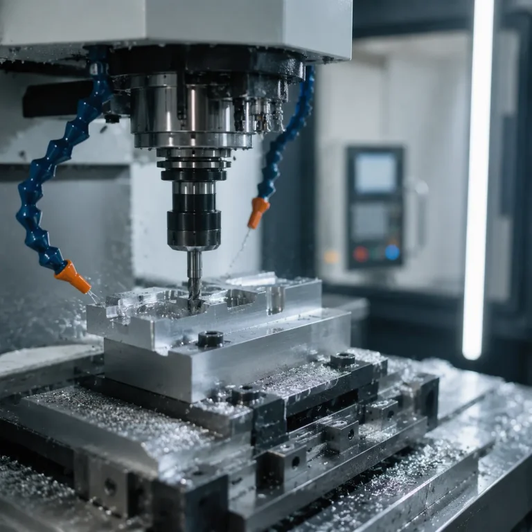
If you are trying to scale your production or need precision parts that match your exact specs every single time, manual machining just won’t cut it. That is where computer numerical control milling steps in. CNC milling is a subtractive manufacturing process that uses pre-programmed computer software to dictate the movement of factory tools and machinery. Instead of a machinist manually turning handwheels, a digital file guides high-speed cutting tools to shave material away from a raw block, turning it into a finished, high-tolerance part.
The Evolution to Automated CNC Systems
Milling has come a long way from its manual roots. Traditionally, operators guided a milling cutter by hand, which meant higher human error, slower production, and limitations on complex shapes. The shift to automated CNC systems revolutionized metal fabrication. By blending mechanical power with digital precision, modern CNC machining eliminates human variance, dramatically speeds up lead times, and allows us to repeat complex designs with absolute machining tolerance consistency.
Core Components of a CNC Milling Machine
To understand how these machines deliver such extreme precision, it helps to look at the core architecture driving the process:
- The Controller: The brain of the machine. It reads the G-code (the programmed instructions) and translates it into precise electrical signals for the motors.
- The Spindle: The heart of the cutting action. It holds and rotates the end mill or other cutting tools at high speeds to chip away material.
- The Axes: Motorized linear and rotational paths ($X$, $Y$, $Z$, and sometimes more) that move either the machine head or the workpiece to execute cuts from multiple angles.
- The Workholding: Heavy-duty vises or fixtures that secure the raw material tightly to the machine bed, preventing any vibration or shifting during high-force operations.
Types of CNC Milling Machines
Choosing the right configuration depends entirely on part complexity, production volume, and material size. We design and utilize a variety of CNC milling setups to balance cost and production capability.
3-Axis vs 4-Axis vs 5-Axis CNC
We classify milling machines primarily by their directional movement. More axes allow for more complex geometry without repositioning the workpiece.
- 3-Axis Milling: The tool moves along the traditional X, Y, and Z axes. This is our go-to for standard, flat-surfaced parts that require straightforward subtractive manufacturing.
- 4-Axis Milling: Adds a rotary axis (A-axis) around the X-axis. This allows us to rotate the part for continuous cutting, making it ideal for engraving or cutting slots around a cylinder.
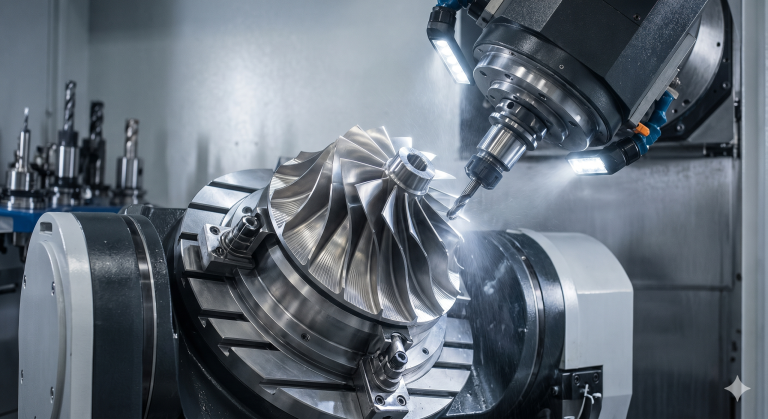
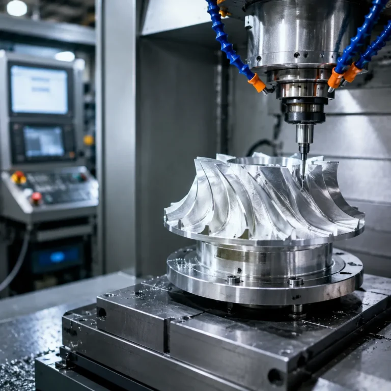
- 5-Axis CNC: Adds rotation on two axes simultaneously. This configuration offers unmatched precision for complex geometries like turbine impellers or medical implants, cutting production time by eliminating multiple manual setups.
Vertical Machining Center vs Horizontal Machining Center
The spindle orientation heavily influences how we approach chip evacuation, part weight, and overall footprint.
| Machine Type | Spindle Orientation | Best Used For | Key Advantage |
|---|---|---|---|
| Vertical Machining Center (VMC) | Vertical (Top-down) | Flat plates, toolroom work, short runs | Low initial cost, easy to set up and monitor |
| Horizontal Machining Center (HMC) | Horizontal (Side-mounted) | High-volume production, heavy parts | Gravity assists chip clearing, faster cycle times via tombstone fixtures |
Gantry Mills and Router-Style CNC Machines
When oversized parts or large sheet materials enter our production floor, standard machining centers hit their size limits.
- Gantry Mills: These heavy-duty systems use a bridge-like structure moving over a fixed bed. We rely on gantry mills for massive metal fabrication projects where part weight or footprint makes a standard machine impractical.
- Router-Style CNC: A lighter, high-speed variant of the gantry mill. These machines excel at high-speed trimming and cutting of larger panels made from aluminum, plastics, or composites.
Common CNC Milling Operations
When we run projects in our shop, we use subtractive manufacturing to carve out precise shapes from raw stock. Depending on the design, we rely on a few versatile CNC milling operations to get the job done right.
Face Milling vs. Peripheral Milling
- Face Milling: We use this to cut flat surfaces on the top of the workpiece. The milling cutter faces downward, cleaning up the material to create a perfectly smooth, flat finish.
- Peripheral Milling: This focuses on the sides. The outer edges of the tool cut away material, which is ideal for squaring up a block or machining deep outer slots.
End Milling, Slotting, and Pocketing
- End Milling: This is our go-to for versatile cutting. An end mill can cut in all directions, allowing us to profile shapes, create vertical walls, and carve intricate details.
- Slotting: We use specific passes to cut channels or grooves directly into a part.
- Pocketing: This operation hollows out internal enclosed areas, removing bulk material while maintaining tight machining tolerance limits on the internal walls.
Holemaking: Drilling, Boring, and Tapping
- Drilling: The quickest way to plunge straight down and create initial holes.
- Boring: If we need a highly accurate, perfectly round hole with a custom diameter, we use a boring tool to enlarge an existing drilled hole.
- Tapping: This operation cuts internal threads inside a hole so it can accept screws and bolts during final assembly.
Best Materials for CNC Milling
Choosing the right material is the first step we take to ensure a successful run in subtractive manufacturing. Different materials react uniquely to a milling cutter, impacting production time, tool life, and final costs. We break down the most common options we use in our shop.
Metals for Metal Fabrication
- Aluminum (6061, 7075): The ultimate crowd-pleaser. It machines incredibly fast, offers excellent corrosion resistance, and is highly cost-effective for both prototyping and production.
- Steel & Stainless Steel (1018, 304, 316): Known for high strength and durability. It requires rigid setups and slower speeds to prevent work hardening.
- Titanium: Lightweight and incredibly strong, but a challenge to machine. It demands sharp tools and precise control to manage high heat generation.
- Brass: Highly machinable with excellent electrical conductivity. It chips easily during cutting, leaving a brilliant surface finish.
Plastics and Composites
- Delrin (POM): Our go-to plastic for precision parts. It is highly stable, easy to cut, and holds tight tolerances beautifully.
- ABS (Acrylonitrile Butadiene Styrene): Impact-resistant and affordable, making it perfect for structural prototypes before moving to metal.
- Polycarbonate (PC): Incredibly tough and transparent, though it requires careful stress-relieving to avoid cracking during heavy CNC machining.
Material Hardness, Feed Rate, and Tool Wear
Material hardness dictates our entire machining strategy. Harder materials require a strategic balance between spindle speed and feed rate to protect the end mill from premature failure.
| Material Type | Relative Hardness | Optimal Feed Rate | Tool Wear Risk |
|---|---|---|---|
| Aluminum | Low | High | Low (Prone to gumming) |
| Plastics (Delrin/ABS) | Very Low | Very High | Minimal |
| Steel | Medium to High | Moderate to Low | Moderate (Thermal shock) |
| Titanium | High | Low | High (Abrasive wear) |
Pro Tip: Harder raw stock increases cutting forces. To combat tool deflection and chipping, we drop the cutting speed, use robust workholding setups, and select advanced tool coatings to keep our lines running smoothly and efficiently.
The Step-by-Step CNC Milling Process
Transforming a raw block of material into a precision finished part relies on a structured, automated workflow. As an established shop, we break this CNC machining process down into four critical stages to guarantee exact machining tolerance and flawless execution every time.
1. Creating the 3D CAD Design
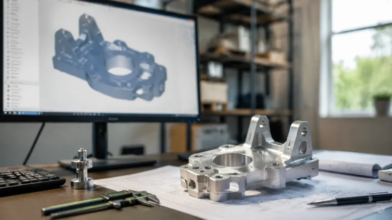
Everything starts with a digital blueprint. We use Computer-Aided Design (CAD) software to build a highly accurate 3D model of your part. This digital file defines the exact dimensions, geometries, and features required for the final product.
2. Converting CAD to CAM for G-code Generation
Once the design is locked in, we import the 3D model into CAD CAM software. This software translates the visual geometry into a language the machine understands: G-code. This specialized code instructs the machine on exactly how to move, dictates the spindle speed, and sets the precise feed rate for the cutters.
3. Setting Up the Machine, Workholding, and Tooling
Before cutting any material, we prepare the vertical machining center or multi-axis mill. This physical setup requires absolute precision:
Workholding: Securing the raw material (billet) tightly using heavy-duty vises, fixtures, or vacuum tables to prevent shifting.
Tooling: Loading the required cutters—like a specialized milling cutter or a high-performance end mill—into the machine spindle.
Zeroing: Calibrating the machine’s X, Y, and Z axes so the program knows the exact location of the raw material.
4. Executing the Program and Post-Processing
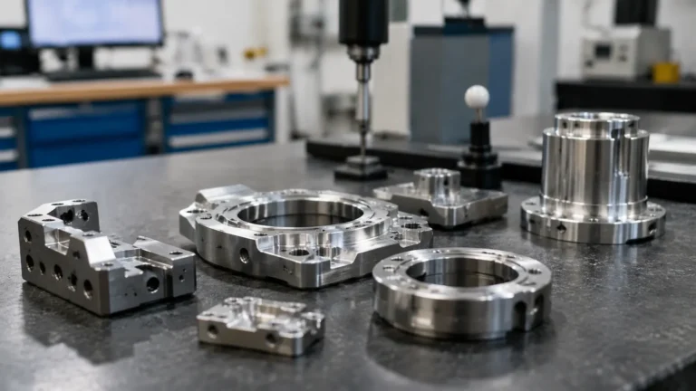
With everything locked down, we run the computer numerical control program. The machine takes over, executing the precise subtractive manufacturing steps to carve away excess material. After the milling cycle finishes, we perform post-processing. This includes removing the part, deburring sharp edges, and conducting a final quality inspection to verify that all dimensions perfectly match the original design.
Essential CNC Milling Tools and Cutters
Choosing the right milling cutter determines the accuracy, surface finish, and speed of your CNC machining projects. We use a variety of specialized tools in our shop to handle everything from rapid material removal to ultra-precise detailing.
End Mills: Flat, Ball Nose, and Bull Nose
The end mill is the absolute workhorse of CNC milling. Each type serves a distinct geographic and geometric purpose on the workpiece:
- Flat End Mills: Featuring square tips, these are our go-to tools for cutting flat surfaces, slotting, and plunging straight down into material.
- Ball Nose End Mills: Built with a hemispherical tip, these are ideal for 3D contouring and machining complex, curved geometries without leaving stark steps.
- Bull Nose End Mills: Blending a flat bottom with radiused corners, these provide high strength, reduce corner chipping, and leave flat bottom surfaces with smooth corner blends.
Face Mills and Fly Cutters
When we need to flat-machine wide open surfaces with extreme efficiency, standard end mills won’t cut it.
- Face Mills: These large-diameter cutters utilize indexable carbide inserts. They quickly flatten large raw blocks, establishing a perfectly flat reference plane.
- Fly Cutters: Operating with a single tool bit, fly cutters require less power but sweep a wide path, delivering a mirror-like, ultra-smooth surface finish on metals.
Roughing Cutters vs. Finishing Tools
To optimize cycle times, we separate the machining process into two distinct stages using specialized tooling:
| Tool Category | Design Characteristics | Primary Purpose |
|---|---|---|
| Roughing Cutters | Scalloped or wavy tooth profiles | Rapidly pigs out bulk material into a close approximation of the final shape, breaking chips easily. |
| Finishing Tools | High flute count, sharp continuous edges | Takes light, precise final passes to hit exact machining tolerances and flawless surface finishes. |
Tool Coatings for Extended Life
Uncoated tools wear down rapidly when facing tough materials. We rely on advanced chemical coatings to handle heat and abrasion, allowing for faster spindle speed and feed rate adjustments:
- Titanium Nitride (TiN): A classic, gold-colored general-purpose coating that increases hardness and heat resistance for steel and plastic fabrication.
- Aluminum Titanium Nitride (AlTiN): A dark, high-performance coating that thrives under extreme heat. It forms a protective aluminum oxide layer at high temperatures, making it indispensable for milling hard alloys like stainless steel and titanium without premature breakdown.
Speeds and Feeds in CNC Milling
Getting your spindle speed and feed rate right makes or break your part. If you run the machine too fast, you will melt the milling cutter. If you run it too slow, you rub the metal instead of cutting it, which destroys the tool just as fast. We manage these cutting variables to maximize tool life and get the exact machining tolerance required.
Core Cutting Terms Explained
- SFM (Surface Feet per Minute): The linear speed at which the cutting edge of the end mill moves across the material. This is completely dependent on the material you cut. Aluminum allows for high SFM, while titanium requires a much lower SFM.
- Chip Load (Feed per Tooth): The thickness of the material chip that each individual flute of the milling cutter shears off.
- RPM (Rotations Per Minute): How fast the machine spindle spins.
- IPM (Inches Per Minute): How fast the table drives the raw material into the spinning tool.
Speed and Feed Calculations
We use two primary formulas to set up our computer numerical control programs before generating G-code.
| Variable to Calculate | Formula | Key Inputs |
|---|---|---|
| Spindle Speed (RPM) | (SFM × 3.82) / Tool Diameter | Recommended material SFM, Tool diameter |
| Feed Rate (IPM) | RPM × Chip Load × Number of Flutes | Calculated RPM, Recommended chip load, Flute count |
Preventing Tool Breakage and Chatter
CNC machining issues like chatter (heavy vibrations) and snapped tools happen when your parameters are out of sync. We use these precise adjustments to keep the CNC milling process stable:
- To eliminate chatter: High-pitched screaming usually means the tool is vibrating. Reduce the spindle speed or increase the feed rate to force the tool to take a heavier chip, stabilizing the cut.
- To prevent tool breakage: Clear out the chips. Recutting trapped chips snaps an end mill instantly. Use high-pressure air blasts or flood coolant to flush the pocket.
- Adjust for tool stick-out: The further an end mill extends from the holder, the more it deflects. Keep tools short and rigid to maintain a clean surface finish and prevent sudden tool failure.
Advantages and Limitations of CNC Milling
When we invest in CNC machining for production, we have to weigh the incredible capabilities against the practical constraints. Like any subtractive manufacturing method, CNC milling excels at specific tasks but carries distinct trade-offs in cost and material usage.
Major Advantages of CNC Milling
- Extreme Machining Tolerance: We routinely achieve tight tolerances down to +/- 0.005 inches (0.127 mm) or better, ensuring exceptional precision.
- High Repeatability: Once a program is set, the machine replicates the exact same part thousands of times without deviation.
- Complex Geometries: Advanced 5-axis CNC setups allow us to cut intricate shapes, deep pockets, and compound angles that are impossible with manual machines.
- Material Versatility: We can switch seamlessly from metal fabrication (like aluminum and steel) to engineering plastics using the same platform.
Key Limitations to Consider
| Limitation | Impact on Production | Our Mitigation Strategy |
|---|---|---|
| Initial Setup Costs | High upfront expense for programming, fixtures, and tooling. | Best suited for mid-to-high volume runs to amortize setup costs. |
| Material Waste | Subtractive process chips away raw stock, creating scrap. | Optimize nesting and recycle metal chips to recover costs. |
| Undercut Restrictions | Standard cutters cannot easily reach certain internal hidden geometries. | Modify part designs using CAD CAM software to avoid complex undercuts. |
CNC Milling Troubleshooting and Maintenance
Even the best CNC machining setups run into hiccups. When your parts aren’t coming out perfectly, or your machine sounds strained, use this quick guide to get your CNC milling operation back on track.
Fixing Poor Surface Finish and Inaccuracies
If your finished parts look rough or miss their machining tolerance, look at these three common culprits:
- Chop Up the Feed Rate: A surface that looks torn often means your feed rate is too high or your spindle speed is too slow. Drop the feed rate to give the milling cutter time to slice cleanly.
- Check the Workholding: If your part is moving even a fraction of a millimeter in the vise, you will get chatter marks and dimensional inaccuracies. Secure your workholding fixtures.
- Dull End Mill: A worn tool rubs instead of cuts. Inspect the edges of your end mill and replace it if you spot chipping.
Preventing Tool Deflection and Overheating
Tool deflection (bending) and overheating destroy both your parts and your tools.
| Issue | Cause | Fix |
|---|---|---|
| Tool Deflection | Long tool stick-out or heavy chip load | Use a shorter end mill, reduce the cut depth, or switch to a thicker tool. |
| Overheating / Burning | Lack of lubrication or wrong speed | Increase coolant flow or use compressed air. Ensure your spindle speed isn’t too high for the material. |
Daily and Weekly Machine Maintenance Routines
To keep your computer numerical control systems running with high precision, we follow a strict upkeep schedule.
Daily Checkpoints
- Clear the Chips: Wipe down the ways, enclosures, and workspace. Do not let chips pack tightly around the moving axes.
- Check Fluid Levels: Top off the way lube and check your coolant concentration.
- Wipe the Spindle Taper: Clean the spindle taper with a clean cloth to prevent tool holder runout.
Weekly Checkpoints
- Inspect Filters: Clean or replace the air filters on the electrical cabinet to prevent overheating.
- Grease the Guide Rails: Apply the manufacturer-specified grease to the linear guides and ballscrews.
- Check for Leaks: Inspect hoses and fittings for any signs of hydraulic or coolant leaks.
CNC Milling FAQs
When we talk to shop owners and engineers about subtractive manufacturing, a few common questions always pop up. Here are the straight answers to the most frequent queries we get about CNC milling.
CNC Milling vs CNC Turning
The main difference comes down to which part moves: the tool or the workpiece.
| Feature | CNC Milling | CNC Turning |
|---|---|---|
| Mechanism | The cutting tool rotates while the raw material stays fixed on the bed. | The raw material rotates at high speeds while a stationary tool cuts it. |
| Best For | Square, rectangular, and complex asymmetrical shapes. | Cylindrical, round, and symmetrical parts like shafts or bolts. |
| Machine Used | Vertical machining center (VMC), horizontal machining center (HMC), or gantry mill. | CNC lathe or turning center. |
CNC Machining Tolerance & Accuracy
A standard commercial CNC milling machine is incredibly precise. You can expect standard machining tolerances around ±0.005 inches (0.127 mm) to ±0.001 inches (0.025 mm). High-end setups and experienced machinists can achieve tight tolerances down to ±0.0002 inches (0.005 mm) for critical aerospace or medical applications.
Material Compatibility
CNC mills can cut an enormous variety of materials, but they cannot cut absolutely everything. The material must be rigid enough to withstand workholding clamping forces and the cutting impact without crushing.
- We easily mill: Metals (Aluminum, Steel, Titanium, Brass), plastics (Delrin, ABS, Polycarbonate), and solid composites.
- We avoid or require specialized setups for: Rubbers (too flexible), extremely brittle ceramics (they shatter), and hardened glass.
CNC Milling Machine Costs for Small Shops
The investment required to bring computer numerical control capabilities into your shop depends entirely on your production needs.
- Desktop / Entry-Level Mills: $3,000 to $10,000. Perfect for prototyping, light plastics, and soft metals like aluminum.
- Mid-Range Toolroom Mills: $20,000 to $50,000. Great for small job shops handling regular steel and aluminum fabrication.
- Industrial Vertical Machining Centers: $60,000 to $150,000+. Essential for high-volume, continuous production and holding ultra-tight tolerances day in and day out.